|
Part 5: Constructing the Airframe |
|
|
|
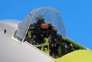
My next step was constructing the airframe. The cockpit fit snugly into the right fuselage half, as did the firewall with a little trimming to the locator tabs and slots. Dry fitting the fuselage halves showed that the engine mounts can be installed through the front of the fuselage, which will permit me to install it in the final assembly. After assembling the control surfaces, I glued the fuselage halves, main and outrigger floats, wings, and horizontal tail planes with Tenax 7R. The fit was very snug on all of these subassemblies, and required only sanding to remove any trace of a seam. For such large parts, I was surprised and happy when everything lined up and left no gaps, other than the area of the fuselage plug for the Rufe's vertical stabilizer. This small gap was filled with CA. While there are very few panel lines to re-scribe, there are a plethora of recessed rivets. As a result of the molding process, these become less distinct where the fuselage halves join. I used a compass needle to replace and redefine the lost rivets. |
| The gunsight was a bit of a disappointment. It is molded in clear styrene, which includes the sighting glass. The mold parting line was very prominent, so I decided to replace the "glass" with Squadron's clear "Thermaform." The prominent ring sight is molded as a solid disc of gray styrene. I replaced it with a photo etched sight from a 1/48 Verlinden Luftwaffe gun set. While it is slightly under-sized, it looks a lot better than the kit item. I also added a bead sight from copper wire. To protect these items, I installed the windscreen after dipping it in Future and masking it with Scotch "Invisible" (frosty) tape. There is a vertical gap here, which must be filled. |
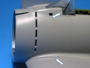
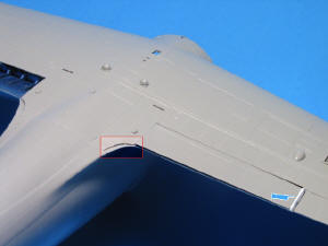
| Joining the wing to the fuselage presented some areas that will need further attention. There is a step between the fuselage fillet and upper wing in one spot. I don't believe this is "builder's error," as the rest of the wing profile matches well. The seam at the junction of the lower wing to the fuselage is the worst fit on this kit. I chose to match the convex portion between these two parts, which left a step at the flatter portions next to the bulge. Filling, sanding, and replacing more rivets will correct this. There is also a major step in the area of the lower fillet. This part of the lower wing could have been molded wider, as there is a noticeable step on the fuselage portion of the lower wing fillet. I have cut pieces from sheet styrene, in the shape of a crescent, to fill in these areas. |
|
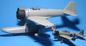
Probably as a result of making them movable, the flaps do not quite span the openings in the wings. I have cut pieces of sheet styrene to fill the gap here. The hinged control surfaces, while easy to assemble and install, do not stay in position very well. I have chosen to glue mine in place. I dry fit the main and outrigger floats, along with the wing and engine / cowl, to the fuselage in this comparison shot. The A6M2 Type 21 is 1/48, and gives some indication of the size of this assembled kit. The floats all fit well enough to not require any filler, and can be added after the painting and finishing are done. Make sure that you have enough room on your bench for this kit after you have installed the wings. The trailing edges are sharp, and could be dented easily. |
| In the next installment, I will be painting the model. I have some discontinued Aeromaster acrylic Nakajima Navy Green and Gray paint left. I have chosen the scheme of "NI - 112." |
|
Information, images, and all other items placed electronically on this site are the intellectual property of IPMS/USA ®. |


