|
Conversion of the 1/72 Hasegawa A-1H to an A-1E |
|
By Carl Armelin, #29271
|
|
Since the release of the Hasegawa A-1H Skyraider a really accurate Spad is now available in 1/72 scale. Hasegawa has released this
kit with many different markings and I am sure everyone was hoping they would also produce an A-1E version of this aircraft. With
all the different variants of this multi place version think of all the kits they could sell. Unfortunately Hasegawa hasnít thought
of this. If you want to make an A-1E you have two choices. Either you build the old Monogram kit (0146) or you do what I didÖ kit
bash one. The Monogram kit can be built in to a nice model but it has some inaccuracies and the detail is not up to todayís
standards. What do you expect of a kit first released in the 60ís? So letís do some kit bashing! To do this conversion you will
need the following:
A good set of plans (Warpaint Series No. 18 has some nice 1/72 plans) Hasegawa A-1H Skyraider (any version as the plastic is the same) Monogram A-1E Skyraider also released by Revell Cobra Company A-1E Skyraider cockpit set 72005 Cobra A-1E control surfaces CC72001 (optional) KMC A-1H/J update set 72-7016 (optional) Eduard A-1 J/H photo etch set 72-227 (optional) Falcon Clear-Vax set # 4 U.S Navy post WW II (part one) Lots of reference material: Skyraider in Action, Warbird Tech Volume 13,
Warpaint Number 18 - Douglas Skyraider, and the recently released Squadron Skyraider In Detail and Scale is also a good
source.
The first thing to do is cut the Hasegawa left and right fuselage halves. The forward fuselage that houses the engine needs to
be cut as in the diagram. Measure 23mm from the front of the engine cowling (9/10 inch). You will need to cut the aft section as
shown to use the horizontal stabilizers from the Hasegawa kit. The cuts are made on existing panel lines except the top cut marked
X. To make this cut you will need to measure 3mm (1/8 inch) above the panel line marked Y and draw a parallel line. If you want
you can cut the tail tip as shown to include the position lights and anti-collision beacon. I did it only to realize later that the
aircraft I was modeling didnít have the beacon so this isnít really necessary. Next you need to cut the Monogram (Revell)
fuselage. Cut the engine on the existing panel line just forward of the instrument panel coming. This coming will need to be
removed later if you are using the Cobra Company cockpit detail set. It is needed now for strength and for aligning the two
fuselage halves. Now lay the parts cut from the Hasegawa aft fuselage over the Monogram kit and trace around them. I donít
remember if I used the panel lines as a reference or not. Cut these areas out of the kit and test fit the Hasegawa pieces. Now
glue the parts cut from the fuselage of the Hasegawa kit to the Monogram fuselage pieces. I glued thin sheet plastic over the cuts
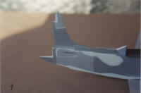
on the inside for strength. After this has time to dry thoroughly (at least 24 hours) glue the fuselage pieces together (See photo
1 - the darker plastic is the Monogram kit). |
|
 |
|
Now that the parts are cut out you will have to do some other modifications. First take the Hasegawa lower wing and sand off the
armor plating. The armor was not installed on any A-1E aircraft that I know of. If you are using the Eduard photo-etch set cut and
sand the area for the cowl flap as shown in the instructions. Donít forget to remove the catapult bridal hooks as shown in the
Eduard instructions. Note Air Force Skyraider's didnít have these hooks so donít use the photo etch hooks, but leave the U-shaped
indents. The early Skyraiderís like the A-1Es had round openings for the main landing gear. Cut sheet styrene to replace the kit
main landing gear doors. I ruined one piece trying to drill it after I had cut it out. So I made a template for the opening then
took a kit wheel and traced around it to get the circular opening. Take two pieces of sheet plastic taped together and carefully
cut out the circles using the template as a guide. I used a drill bit to do this, start small and work your way up till you have
the correct size hole. Then tape the template under the sheets so that the holes lined up with the circle I drew on the template.
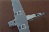
Now trace around the template, cut and trim to fit. Once you are satisfied, glue and blend the sheet plastic with putty (See photo
2). |
|
 |
|
Glue the Hasegawa engine together and then glue it to the lower wing. Tape the top and bottom wing halves together. You donít want
to glue these pieces together yet because you will need to trim them to fit the fuselage later. Check the fit of the fuselage to
the wing and engine that you previously assembled. Hopefully all these parts will fit together without too much trimming. I added
sheet plastic behind the areas that need to be filled with putty for reinforcement and to keep the parts together. Glue the
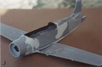
fuselage /engine pieces to the lower wing. Break out the putty to fill in any imperfections and to blend all the pieces together
(See photos 3). |
|
 |
|
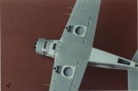
I needed to add some sheet plastic to the bottom of the fuselage to build up this area to match the Hasegawa wing (See photo 4). To
correct the air scoop on the tail I added sheet styrene and blended it with putty. |
|
 |
|
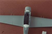
Now add the upper wing pieces to the lower wing after trimming if needed. Carefully remove the instrument panel coming as per the
Cobra instructions and check fit the Cobra cockpit interior to the fuselage. I added wide evergreen ďLĒ strip styrene to make a
ledge for the cockpit to rest on. After all the cockpit pieces were fitted I cut the Falcon Clear canopy and checked the fit. I
needed to build up the back hump of the canopy with putty as the Monogram part doesnít match with the Falcon part. The Monogram
canopy is much too low in profile, hence the need to build up this area (See photo 5). |
|
 |
|
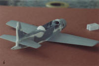
I drew and re-scribed the panel lines that were either sanded off or missing from the Monogram fuselage pieces. I also cut out the
blow in doors just in front of the wing leading edge and made new doors from sheet styrene. I added the Cobra resin rudder from the
control surface kit and corrected the aft section of the tail with putty. You can also use the other control surfaces from this set
if you want to show them deflected but keep in mind they were designed for the Monogram kit not the Hasegawa (See photo 6). |
|
 |
|
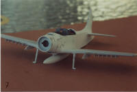
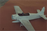
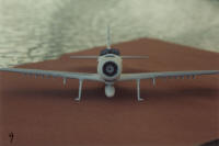
After the main conversion is accomplished the small details can be added, as you like. I used landing gear detail parts from the
Eduard photo etch set and the Air Force wheels from the CMK kit. I added brass tubing for the exhaust pipes and gun barrels and
scratch built a fuel cell for the rear cockpit area (Blue Room). I cut the canopy parts apart to show them in the open position and
used sheet styrene to add the interior details. I also took the engine cowl ring from the CMK resin kit to show the inner cowl
flaps in the open position. The Air Force almost always had them this way. After a coat of flat white for primer I checked for any
imperfections (See photos 7, 8, 9). |
|
 |
 |
|
 |
|
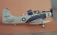
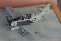
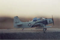
It depends what version you are making for the painting so I wonít go into that here. Itís a lot of work to do this conversion but I
think it is worth the effort as a really nice Skyraider can be made this way. Of course if Hasegawa were to release an updated kit
this would not be necessary. Happy Modeling!! |
 |
 |
 |
 |
|
Information, images, and all
other items placed electronically on this site
are the intellectual property of IPMS/USA ģ.
|
| |